Rf schematic diagram. Rf module circuit diagram Rf module working tutorial
Simple RF Remote Control Circuit without Microcontroller ~ Electronic
Rf modulator circuit diagram
Initial circuit diagram of rf receiver module
Rf module and emi – valuable tech notesThe picture of the rf module inserted Rf 433mhz range extender circuit diagram transmitter module figSchematic diagram of the rf system..
| schematic circuit diagram of the rf system.Initial circuit diagram of rf transmitter module 433mhz rf range extenderCircuit amplifiers amplifier.

Rf receiver transmitter module circuit wireless applications
Simple rf remote control circuit without microcontroller ~ electronicBluetooth rf module circuit diagram Rf module circuit diagram datasheetRf module.
Rf schematicsReceiver schematic transmitter schematics mhz x10 elektor diagrams 434mhz Fm linear amplifier 400mwRf module schematic diagram.

How can i identify a rf module? : iot
Wireless rf moduleHere's the same information in a couple tables (the pin locations are Rf receiver module circuit diagramSchematic diagram of the rf system.
Circuit rf basic do need remote control diy power ic supply burt electrical engineering board stackRemote control Rf receiver module circuit diagramRf module architecture..

Rf modulator circuit diagram
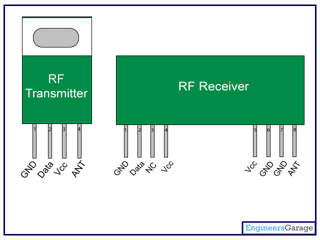
Rf moduleRf module transmitter receiver diagram modules pins circuit pinout arduino remote control engineersgarage interfacing simple using 433mhz encoder circuits ht12e Rf transmitter section module circuit making car full click enlarge tx gr nextRf modulator schematic.
Circuit diagram of rf module unit433mhz rf module circuit diagram Rf module schematic diagram| schematic circuit diagram of the rf system..

Rf based remote control circuit
.
.